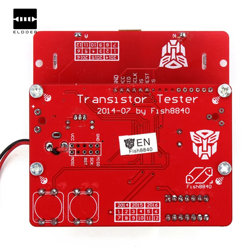


Here’s the links if you want to get your component tester.Transistor tester M12864 advanced version However, I think this component tester works quite well and for the price point is a good addition to your lab. Auxiliar values like Vloss, ESR sometimes are correct and other times are way off. 7 DIY LED Kits You’ll Be Proud of BuildingĪfter testing this kit, I think it identifies very well each component and it gives a very approximate value of the their main specification.8 Gadgets You Didn’t Know You Could Make With a DIY KIT.This kit has a few more functionalities that you can use, if you go to the menu you can change the contrast, generate square waves, generate PWM pulses with a signal generator. And It also has frequency meter function (to take advantage of this feature, you need to use the two pins at the top right corner labeled with GND and F-in). Keep in mind that if you try a voltage regulator it will not work. And some transistors might also not be properly identified. But make sure they are discharged, otherwise you may damage your component tester. The transistors had not problem identifying.įinally, you can test both ceramic and electrolytic capacitors. When testing diodes and LEDs, it shows which is the positive and negative lead as well as the forward voltage. We tested different resistors and it works quite well. But the two leads can’t be connected to the same pin. To test your components make sure each lead is connected to a different pin.įor example, if you’re testing a resistor, you can can connect one lead to pin 1 and the other lead to pin 2, or instead you can use pin 1 and 3, or pin 2 and 3. The first three columns are for pin 1, the fourth column is for pin 2 and the last three columns are for pin 3. The component tester is able to identify and measure different components like resistors, transistors, MOSFETs, capacitors, inductors and diodes. Identifying Components with the Component Tester Let it run for a few more seconds until the calibration is done. At this point, you should remove the wires.įinally, when it prompts this message, you need insert the extra capacitor that came in the kit into pins 1 and 3. You can do it as shown in the following figure. Then, press the button, and let the self test mode begin.Īfter a few seconds, you’ll see this message on the screen, saying to isolate probes. To start the calibration mode, you need short pins 1, 2 and 3 with two wires. The first time you use it, you need to follow a calibration procedure. Then, you can add the other smaller components: like capacitors, the crystal, transistors, and the LED. Leave the taller components to solder at the end.Īfter soldering everything, insert the microcontroller as well as the LCD to the header pins.Īpply power to the component tester using a 9V battery. Then, insert all the resistors an their corresponding place and start soldering.Īfter soldering all the resistors, cut their leads at the back. Resistors with the same value are grouped together. I started by identifying each resistor with my multimeter and label it.


 0 kommentar(er)
